Federbolzenschrauben
für Vestibulär-Bewegung und Derotation*
von Zähnen
Spring-bolt
screws for vestibular movement or derotation* of
teeth
Pistons-ressorts
pour mouvement vestibulaire ou dérotation* des dents
 Die
Vorteile der Federbolzenschrauben für diese Aufgaben sind
ihre Kleinheit, ihre gut dosierbare Kraftabgabe und
besonders ihr einfacher
nachträglicher Einbau in
Platten (oder auch in FKO-Geräte).
Die
Vorteile der Federbolzenschrauben für diese Aufgaben sind
ihre Kleinheit, ihre gut dosierbare Kraftabgabe und
besonders ihr einfacher
nachträglicher Einbau in
Platten (oder auch in FKO-Geräte).
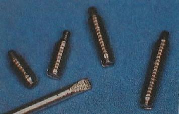
Federbolzenschrauben gibt
es in mehreren Längen (4, 6, 8mm), aber leider nicht in mehreren
Federstärken, wie es für verschieden große Zähne
wünschenswert wäre. Federbolzen von gleicher Größe
und Stärke fand ich neulich in den Verbindungsstiften, die das
Armband meiner Uhr mit der Uhr selbst verbinden - soviel zu ihrer
mutmaßlichen Herkunft.
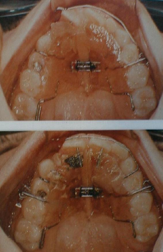
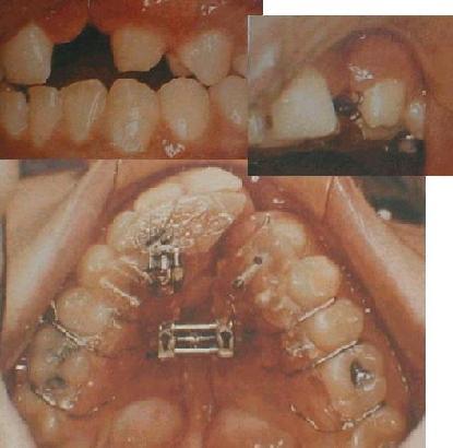
Im ersten Beispiel
wird bei laufender Behandlung ein drohender Kreuzbiss eines
wachsenden Eckzahnes verhindert (oben links in den Mund-Aufnahmen),
indem dahinter eine Federbolzenschraube „nachgerüstet“
wird (oberes rechtes und großes Bild). Der enge und
asymmetrische Oberkiefer dieses 14-jährigen Spaltpatienten ist
durch die Platte bereits auf dreifache Weise geformt worden:
„Querdehnung“ (eigentlich Wachstumsanregung) und Vorschub
des Frontsegments (beachte, wie weit die Quer- und die kleinere
Frontsegment-Schraube schon ausgefahren sind!) sowie mit
Federbolzenschrauben selektive Vestibulärbewegung des 4ers und
5ers rechts im Bild.
|
|
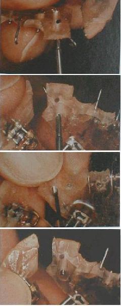
Die
Platzierung der Federbolzenschraube für den Eckzahn wird auf
der Platte angezeichnet, und dann wird, in der Bilderserie von
oben nach unten, für sie ein Kanal gebohrt (ein 1.4mm
Bohrer hat sich bewährt), darin ein Gewinde geschnitten
(Gewindeschneider vom Hersteller) und dann die Schraube so weit
eingedreht, dass der Bolzen wirksam wird. Steht ihr Kopf dann wie
hier noch über, so sollte er mit Wachs abgedeckt werden, um
Irritationen zu vermeiden.
Weiterdrehen erfolgt in der Regel in
360°-Drehungen durch den Arzt. Wird der Halt der Schraube im
Plastik durch ihr Herausdrehen zu schlecht, so kann sie leicht
gegen eine längere ausgewechselt werden.
|
|
|
Beim Ausdrehen eines Zahnes über
eine weite Strecke, wie im 2. Beispiel (nochmal Oberkiefer
eines Spaltpatienten), ist statt Verlängerung eine
Richtungsänderung, d.h. Neu-Einbringung der Federbolzenschraube
vorteilhaft. Für den stärker
verdrehten 1er links im Bild setzt die Federbolzenschraube zunächst
sehr schräg an, damit er nicht unerwünscht protrudiert
wird. So braucht das Gegenlager, das bei Derotationen immer nötig
ist (hier ein Teil-Labialbogen) auch keine große Kraft
aufzunehmen. Im unteren Bild wurde diese Schraube umgesetzt und zwei
weitere wurden nachgerüstet (beim anderen 1er und 3er), nun
allesamt in radialer Richtung. Beachte, wie weit auch hier die
„Dehnschraube“ schon ausgefahren war (ca.
5mm), dass der Vorderbereich des
entstandenen Spangen-Spaltes für besseren Tragekomfort mit
Plastik aufgefüllt wurde und dann im unteren Bild zur weiteren
Verbreiterung wieder aufgesägt wurde.
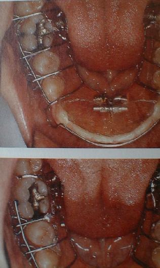
Im
3. Beispiel wird im Unterkiefer der 6er mit einer
Federbolzenschraube ausgedreht. Als Gegenlager dient eine
Balkenfeder. Da die Dreiecksklammer zwischen 6er und 7er dem
Ausdrehen entgegenstand, ist sie im unteren Bild entfernt.
Auf
diese Weise können ebenso im Oberkiefer Molaren ausgedreht
werden. Eine ganz andere „herausnehmbare“
Lösung zum Ausdrehen
selbst großer Zähne (6er, 3er) zeigt schließlich das
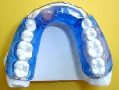
gelbe Bild: Silikon-Setup-Technik, siehe Galerie Teil A.
The
advantages of spring-bolt screws are their tiny
size, well controlable force and especially that they can
easily be added later to a plate or functional appliance which
is already in use.
Spring-bolt screws are available in several
lengths (4, 6, 8mm), but unfortunately not in several strenghts,
which could be useful for teeth of different size. Recently I
found very likewise spring-bolts in the rods that connect the wrist
band of my watch to the watch itself. This to the presumed origin of
spring-bolt screws.
In the first example, a crossbite of
a growing cuspid (see upper left mouth photo) is prevented by adding
a spring-bolt screw in the plate behind it (upper right and big mouth
photos). The narrow and asymmetric upper jaw of this 14-yr
cleft-palate patient has already been shaped by the plate in three
ways: widening of palate and protrusion of incisors (see how wide the
transversal and the smaller frontal screw have been unscrewed!) and
selective buccal shift of the 4 and 5 on the right side in the photo
with spring-bolt screws.
First, the positioning of the spring-bolt
screw for the cuspid is drawn onto the plate. Then, in the little
photo series from top to bottom, a channel is drilled for it (a 1.4mm
drill has proven useful) and a thread is cut in (an appropriate
reamer should be available from the supplier of the screws). The
screw is screwed in until its bolt is in active position. If the head
of the screw then still sticks out, like here, it should be covered
with wax to avoid irritations.
Re-activation should normally be
done in 360°-turnings by the doctor. If the screw loses support
in the plastic during this, it can easily be replaced by a longer
one.
For derotation of a tooth along a larger
distance, like in the second example (one more cleft-palate
upper jaw), a change in screw direction can be preferable over a mere
prolongation. At first (upper photo), the screw pushes the most
severely twisted incisor with a direction that does not unwantedly
protrude it. Subsequently, the counter support, that is always
required for derotations, does not need to absorb high forces. Here,
it is just a long, 1-armed wire spring of normal thickness. Later,
this screw is newly inserted in a more conventional, radial
direction, as are two further screws against the other incisor and a
cuspid. Please note also how wide the expansion screw has been opened
with time (about 5mm), and that the resulting wide slot in the
plastic has been filled up with plastic in its frontal part, for
higher wearing comfort. Then, this new plastic was divided again in
the lower photo for continued expansion.
|
In
the third example a lower 6 (molar) is derotated by a
spring-bolt screw. A wire bar serves as counter support. The
triangular clasp between 6 and 7 is cut off in the lower photo
because it was hampering the derotation.
Upper molars can be
derotated likewise. Finally, a completely different removable
solution for this task is exemplified in the yellow photo: the
silicone rubber set-up technique, see Galerie Teil A for more
details.
Les
avantages des vis pistons-ressort sont leur minuscule
taille, leur force bien contrôlable, et en
particulier ce qu´ils peuvent être ajoutés
plus tard à un appareil (plaque ou fonctionnel) qui est
déjà employé.
|
|
Pistons-ressorts sont disponibles
en plusieurs longueurs (4, 6, 8mm), mais malheureusement pas en
plusieurs forces, ce qui pourrait être utile pour dents de
taille différente. Récemment, j´ai trouvé
des pistons-ressorts identiques, mais sans vis, aux fins des
bâtonnets qui jumelent le bracelet de ma montre avec la montre
même. Ce qui peut indiquer l´origine de ces éléments.
Au premier exemple, un
articulé inversé de la canine sortante (voir la
gauche-dessus des photos de la bouche) est prévenu par
insertion d´un piston-ressort derrière cette canine dans
la plaque ( droite-dessus et grande photo de la bouche). La
maxillaire étroite et asymétrique de ce patient à
palais fendu âgé de 14 ans a déjà été
modelée par la même plaque en trois façons:
expansion du palais et protrusion des incisives (regarde par quelles
distances le vérin écarteur et le plus petit vérin
frontale sont déjà sortis!) et mouvement buccal
selectif du 4 et du 5 par pistons-ressorts à droite de la
photo.
L´emplacement pour le piston-ressort pour la canine
est marqué sur la plaque. Puis, dans la petite série
des photos, un conduit est foré (un foret de 1.4mm convenait)
et ensuite un pas de vis est coupé (un taraud approprié
devrait se vendre avec les pistons-ressorts). Le piston-ressort est
vissé jusqu´a ce que le piston sort de l´autre
coté. Si comme ici la tête du vis dépasse
toujours la surface de la plaque, il faudrait la couvrir de la cire
pour éviter des irritations.
L´activation des
pistons-ressorts s´effectue normalement par le docteur, par
vissements de 360°. Si le piston-ressort commence à
branler en cours de l´activation progressive, il peut
facilement été échangé par un plus
longue.
Pour déroter
des dents par grandes distances, comme au deuxième exemple
(autre patient à palais fendu), il vaut mieux de changer la
direction du piston-ressort. Au début (photo dessus), le
piston-ressort pousse l´incisive qui est la plus distorte avec
une direction diagonale, ce qui évite sa protrusion, et qui
réduit le besoin d´un contre-appui très fort. Il
faut toujours un contre-appui pour les dérotations avec les
amovibles, mais un fil de fer mince suffit en cet exemple. Plus tard,
le piston-ressort est re-positionné, et deux autres sont
ajoutés pour l´autre incisive et la canine, tous dans
directions radiales,
habituelles. Regarde aussi ici la grande
distance d´environ 5mm que l´écarteur est déjà
sorti. La fente résultante dans la plaque a été
remplie au section frontale avec de la matière plastique,
aussi pour éviter des irritations. Plus tard, il fallait
couper cette matière en deux pour continuer l´expansion.
Au
troisième exemple une 6
(molaire) mandibulaire est dérotée par un
piston-ressort contre un appui du fil de fer à l´autre
coté. Puis il fallait découper
le crochet triangulaire entre la 6 et la 7, qui bloquait la
dérotation.
Molaires maxillaires peuvent être
dérotées de même façon. Enfin, la photo
jaune montré en bref une
autre solution amovible pout cette tâche, qui est
completement différente: le modelage de la matière
silicone autour des dents du modèle en plâtre, qui
étaient auparavant mises à droit (set-up
technique). Voir chapitre Galerie Teil A pour plus des
détails.
Quelle: J. Tränkmann, „Die
Federbolzenschraube in der kieferorthopädischen
Plattenapparatur“, Quintessenz Zahntech 19 (1993) 55-60.
zurück
back retour
Letztes
Update dieses Teils +++ last update +++
dernière mise à jour:
02.01.2007